Creating your first level
With this tutorial you are going to learn some of the MaxED basics. Issues like basic modeling, booleaning, exit creation (visibility optimization) and exporting the level to the game are covered. Please refer to other MaxED documentation or other tutorials for additional information .
Start MaxED. Make sure that you have set it up correctly (see "Setting up MaxED") and it is working with the game database. Download the tutorial file (Creating_first_level.zip) to see what will be our goal. Then, it might be best to close the document and start from scratch.
A new document...
By default, MaxED opens an empty level file with no textures and no geometry, just the blue grid and the camera in their default positions.
If you do not already have an empty level file open for some reason, you can get one by selecting File/New...

Few words about modes...
Editing-wise, MaxED is based on different editing modes:
F3 – “Model” - New entities/key points/meshes are created in this mode.
F4 – “Extrude” – This is essentially a polygon editing mode.
F5 – “Transform” – An object editing mode.
F6 – “Texture” - Most of the texture related editing is done in this mode.
F7 – “Exit creation” - Exits are created in this mode
F12 – “Move grid” - Most of the grid functions are available always, but some additional grid manipulation is done in this mode
SPACE – “Move” – The movement mode.Whatever manipulation you want to do to your level, you have to be in the correct editing mode before you can do the right things. Some commands can be done in multiple editing modes for user’s convenience. For example you can do some texture operations in F5 mode as well. You can get a list of available commands in each mode from the “Mode Commands” menu. It only shows the commands of the current mode you are in. You can also get the “Mode Commands” menu by pressing the middle mouse button or CTRL+SPACE in the render window.
Moving around (Move mode)
You can now try moving around in the world. You can look around freely by pressing down LEFT MOUSE BUTTON (LMB) and moving the mouse. Move forwards and backwards by pressing down RIGHT MOUSE BUTTON (RMB) and moving the mouse forwards or backwards. Strafing is done by pressing down SHIFT and moving the mouse.TIP: If you can't move, make sure you are in "Move" mode by pressing spacebar. Note that pressing spacebar multiple times toggles between two types of movement modes. The regular and a so called "Around"-mode. The "Around" mode makes the view move around any given point in the level geometry (pressing and holding LMB initiates horizontal rotation around that point, RMB is for vertical rotation). Since we don't have any geometry yet, we can't use it.
Adding textures
First, you will need to add textures to your level. MaxED handles textures as "materials". There are several material categories to which organize your textures, each with their own properties (sound, decals, etc.), and all textures in a specific category will behave the same in the game. This means that if you put a brick texture to the wood -category, it will emit wood particles when shot, sound like wood when stepped on, and leave a wood decal in the game.
Adding textures to a level can be done in more than one way, but the best way, at least for now (to get our tutorial rolling) is to grab all the textures of another level file, in this case from the example level "creating_first_level.lvl". To do this, select Insert materials from file from the Material menu.
Navigate the selector to the "creating_first_level.lvl", select it and press OK.
After small preprocessing delay, you should see a bunch of textures in the material palette window bottom-left corner of the MaxED window, with texture names and texture sizes shown.
Take a moment to get yourself acquainted with the few materials (textures) you just inserted, notice also that above the material selector there is a pop-up list that shows the current material category. Select also other categories to check out their contents.
When you click a texture with LMB, you make that the current material. The active texture is indicated by a blue highlight.
TIP: If you want to add some of your own textures, you can drag and drop them from windows to material palette or use Insert bitmaps. MaxED can handle JPG, TGA, PCX, SCX and BMP formats, but it is recommend you use jpg, since at its highest quality the difference to, for instance TGA, is almost unnoticeable and the file size still a lot smaller (much of the size of a level comes from the textures). The textures can be of any size, but for compatibility reasons and better performance on some hardware, it is better to keep the dimensions in 2 based figures: 2, 4, 8, 16, 32, 64, 128, 256 etc. As texture memory and rendering speed are always something to consider, texture resolution should not usually exceed 1024 in any dimension.
Right-clicking the material in the material palette will bring up a a menu with lot of settings for materials, but we will jump into that in more detail later.
Creating some room geometry (F3 mode)
By default MaxEd is in wireframe mode. Use F2 to toggle into texture rendering mode (alternatively toggle Mode/Wireframe tick off from the menus). Generally all MaxEd work is recommended to be done in the textured mode and you need the WF mode very rarely, if ever. Try to toggle between the modes now.
TIP: If nothing seems to happen, try right-clicking inside the rendering window first. Some options (like switching modes) in MaxED aren't available before you make the rendering window active by clicking in it. It is recommended that you right-click as this minimizes the risk of accidentally moving something.
Lets adjust the preferences a little before we proceed any further. Open preferences dialog by pressing Ctrl+P.
At this early stage, we do not want to worry about exits or lightmaps. So remove the tick from Exit acceleration and make sure that the radio button at Texture display is set to Only primary texture. We'll get to these issues later, so let's just press OK for now.
Next we’ll create a simple room. Press numpad +/- to adjust grid size, by default it is 0.5 meters so let's make it one meter by pressing numpad + once. You can see the current grid unit in the bottom right corner. Move closer to the grid and turn yourself a little more towards the grid (i.e. look down a little).
Press F3 to switch into Model mode. Click the brick material in the default category if you have not already done so.
Now draw a shape onto the grid. Do this by pressing LMB on the grid points. While drawing, keep an eye on the lower right corner to see the measurements of the shape you’re creating. Draw a 6m x 8m square on the grid.

While drawing, remember that the shape can not intersect itself, a vertex causing this is considered illegal, and MaxED won't let you place such a vertex (the shape will turn red). You can press delete during the drawing to undo last vertex placement. By pressing spacebar or ESC you can cancel the drawing altogether.
When you have placed all the 4 points, press RMB to extrude the shape into a 3D object.
The shape now changes from a 2D shape into a 3D-object with texturing visible (unless you are in WF mode) with the mesh faces pointing inwards, meaning that you see all the faces when you are inside it (these are used for rooms). If you are outside the mesh (like here), the faces that have their backsides towards you get culled and are not visible. We are making a room, so this is exactly what we want.
TIP: From the preferences (“flip faces after mesh creation”) you can set whether all the objects are by default created with their polygon faces pointing outwards or inwards. You can manually flip the object with ‘CTRL-F’ while pointing at the object in F4-mode.

You should also see a new mesh appear in hierarchy list in top-left corner named "New Mesh 00". Right-click the name in the list and select Properties from the menu. You get a dialog with the name on the middle, change this to "Startroom".

If you think that your shape was a complete failure, you can delete the mesh either from the hierarchy list by right-clicking the name and selecting kill, or by going to F5 mode, selecting the room with LMB click and pressing delete.
TIP: You can move around with arrow keys while you are drawing objects outlines in F3 mode. To make use of this while creating bigger, more complex objects, it's a good idea to first point the camera directly towards the grid so the distance to the grid remains the same when moving. Ctrl combined with up and down arrow will advance and back up during drawing.
TIP: If you don't want to model a mesh with volume, but rather just a single polygon, a 2D-object, draw the desired outlines to the grid just as above, but hold down SHIFT when clicking RMB. Note however, that while sometimes useful, 2D-objects are a lot more cumbersome than 3D-objects because they cannot be transformed later as 3D-objects can. If you want a 2D-object in a level that you can fully manipulate in MaxED, make it a 3D-object, and texture all but one face with a dummy texture (any texture that you put in the "dummy" -category). All polygons with this texture will be completely unnoticeable in the game.
Editing room polygons (F4 mode)
You have created a basic form for the room, but it is only one current grid unit thick (1 meter, if that's what you had for the grid size when you extruded the object). That is clearly not enough (Max requires some 2 meters minimum as he is 185 cm tall, and the camera works best if the rooms are some 4 meters or more tall) so we have to extrude the shape a little by modifying its polygons.
Switch into F4 mode, move cursor over the ‘ceiling’ polygon (but do not click) to select a poly (You will see the active polygon indicated by yellow/red outline). Below left you see what might happen when you point at the roof from above, and "select culled polygons" in the preferences is not on: the floor gets selected, not the roof. To select the roof, either move down and look up to see the roof, or even better, use insert key to toggle "select culled polygons" option on/off. Once on, you can select polygons even from their back side as seen on right.

Now you can extrude shape by pressing LMB and dragging mouse up/down. In this case, it may be easier to press arrow keys up/down to get more accurate control. If your grid unit is still 1 meter, press cursor up 3 times to extrude mesh 4 meters high as seen here. If you do not move your mouse, you can keep pressing cursors up/down till you are satisfied. Pressing cursors right/left or RMB would skew the face in relation to active edge (red one) but lets not get into that now.

Congratulations, you have made your first room, you will be making killer levels in no time :-)
Notice that in MaxED usually all of the meshes you make are volumes, not just a bunch of polygons. MaxED is a so called 'solid modeler'. You can not extrude or skew polygons of an object through itself (or any edges), because that would result into illegal volumes and would mess up the Boolean operation functionality. For instance, you can not bring the roof down to absolutely touch the floor -- that would make the walls zero height and the room volume non-existing. You can get closer than one meter though by making the grid unit smaller. You should not also ever delete faces from rooms or anything that you plan to Boolean later. If a face (polygon) is deleted a volume is is no longer defined -- Booleans become impossible. We'll get back to these issues in more detail later.
The Grid (F4/F12 mode)
Before we proceed, you should learn to use the grid a bit better -- it is your most important tool in MaxED.
The grid can be aligned by hovering over a polygon in F4 mode and pressing A (free align) or Shift-A (align in world coordinates). Remember to turn the grid on (numpad *).
Please note that the grid will be placed to the intersection of your camera's normal (a 'beam' away from the middle of the screen) and the polygons plane that you point. You should always look fairly directly to the polygon that you want the grid to be aligned to. If you are in a very low angle, the grid might be placed pretty far as. See the example below left, where the grid is aligned to the floor. The one on the right is a much more successful alignment, as the middle of the screen is better positioned in relation to the plane of the desired polygon.

Practice a little: Move around your model and switch to F4 mode to align the grid. Try to align to another polygon (wall for instance) and move again. Try switching the backface selection on/off by pressing Insert when aligning. Also try to change the grid size (numpad +/-).
Go into the Grid mode by pressing F12. In this mode you can move the grid around with LMB and raise and lower it in steps of one current unit by RMB -- alternatively by using cursor keys and PageUp/PageDown.
Notice the spot in the middle of the grid, that is the grids origin. You need that in some operations, like when you want to place the pivot point of an object.
If you get completely lost, go to F12 mode and press R to reset the grid and the camera to their default positions.
Handling objects, using Booleans (F5 mode)
Let's copy the room mesh to get another room. Go to F5 mode, then select the room by clicking LMB on it. Now copy/paste it by pressing CTRL-C, CTRL-V in a sequence, and move the new room to the desired position with the arrow keys. The copied room is automatically selected after the paste, so you do not have to select it (top left image)
To join the rooms you should create a short corridor between them. Move the camera so that you can see in between the two and enter F3 mode once again. Draw the outline of the corridor. Extrude the ceiling of the corridor to be high enough. Make it 3 meters high (see top-right and bottom-left pictures below). Of course you CAN make doors that are real-life sized (some 1x2 meters), but if you are planning to move around in the level fluently, you should pretty much multiply all real-life measurements by 150%, thus making a "good" door something like 1,5m x 3m in size. Max's collision capsule prevents Max going through an opening smaller than 98 cm in width and some 195 in height.


Now we need to Boolean the meshes together. It's better to stay where you are (between and outside the rooms). Enter F5 mode and click the corridor object with LMB to select it, press U (Union), and click the room on the left with LMB. You get a dialog where you can still change the Boolean operation, or Cancel it altogether. Union the hallway to each one of the room meshes. As a result, you'll have two rooms with a hallway between them.
Placing exits (F7 mode)
For visibility optimization, Max Payne uses exits, which basically are planes that define the boundaries of the rooms. What the engine always draws is everything inside the room you are in, and everything you can see through exits. This means if you didn't make a single exit to a level, the engine would render the whole level all the time regardless of how small portion of it you would see. But don't forget that exit processing also takes time so you shouldn't make too many exits into the level. Typically you make exits to the doorways. So let's make an exit to the doorway of our example level. (note that you can only create an exit so that all of it's edges touch the room object that it is dividing)
Align the grid to the wall with the corridor. Switch to Exit (F7) mode.
Draw the exit along the outlines of the corridor. Place a vertex at each edge position with LMB. Do notice that in this mode MaxED shows polygon and edge selections, just like in F4 mode (Yellow and red lines). The edge that is closest to the mouse cursor is always the one that is selected. Make sure that an edge that intersects with the grid is selected when you click the mouse button.

TIP: If the corridor doesn’t match with the grid you can use A in F3 mode to align grid origin to the selected edge. (Obviously the edge has to be intersecting with the grid).
After drawing the outlines, press RMB to place the exit.
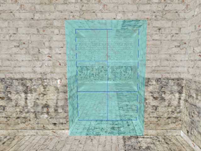
You should now see a ‘Mesh Separated into two by exits’ message on screen. Accept that with OK and you will see the exit appear in the rendering mode showing as a cyan plane between the room and the corridor.
The room gets split into two (look at the hierarchy tree), and now you should have “Startroom01” and “Startrom02” in there. Rename “Startroom01” to “Startroom”.
Exporting level
First let’s add a player Startpoint to the level. Place the grid on the floor of the “Startroom”, and press N to insert a new entity onto the grid. A “New Entity”-dialog will appear. Choose “Jumppoint” from the list. Now group the Jumppoint to the room it’s in by pressing CTRL+E in F5 mode (Autogroup All).
Few words on grouping and hierarchy levels
All the grouping commands you can use are:
G – Group Selected; Select a mesh, press G, and press LMB to the desired parent mesh
CTRL+G - Lift Children; Lifts all the children of the selected mesh up one hierarchy level.
SHIFT+G – Lift This; Lifts the selected mesh up by one hierarchy level.
E – Autogroup; Groups all the meshes inside the selected room to it.
CTRL+E – Autogroup All; Goes through all the rooms in the level and does the above.In MaxED, the level consists of “Rooms” (The topmost meshes in the hierarchy tree), which are separated by exits. All the objects inside a given room are hierarchized to be it's children. This way the engine can do visibility optimization properly. For dynamic content, MaxED uses messages that are sent to specified objects. The objects are defined not only by their name but also by their hierarchy level. For example “::Startroom::Startpoint 00”. Also for animating objects, an animating parent always moves its children along with it. In MaxED, when you select a parent, all it’s children are also selected, and when you move a parent somewhere, all it’s children move too.
Once the necessary grouping and Startpoint adjustments are done, you are ready to take the level to the game. Check the Setting up MaxED -section about the necessary modifications that you might want to make to the game before doing any of the following.
When all that is done, export the level to the .LDB format that the game engine uses. Select “File” -> “Export X_LevelDB…” Click on ok to both questions. Next browse your way through to the game directory, and from there go to: “…\data\database\levels\examples\”-directory. Export your level with the name of my_level.ldb. Alternatively, if you so choose, you can overwrite the basic_room.ldb example so that you will not have to do the following changes into levels.txt
If you decided to use my_level.ldb as the name, you need to edit the levels.txt that we extracted from the ExampleMod (see Setting up MaxED). Opening it up, you will see the topmost level block (basic_room) that is used by the example level. Make a copy of the whole block (copy/paste) so that you have two of them one after the other. Then rename the new block to my_level. Also change the “Level” definition to be my_level.ldb instead of “basic_room.ldb". Below is a part of the file as you now should have it (opened in UltraEdit). Now save the file.

As also described in the Setting up MaxED section, we will have to run Max Payne with some additional command line options in order to get into the developer mode. Create a new shortcut for MaxPayne.exe or modify your previous one:
MaxPayne.exe -developer -developerkeys –window
TIP: Depending on your video hardware, you might have to close MaxED when you run the game. Sometimes it is enough, that you just off the texture rendering (F2) while you are running the game, as having these both open and consuming graphics memory is sure to cause some problems, except perhaps on a very state-of-the-art hardware.
If you overwrote the basic_room.ldb, you can access you level by choosing that menu item in the developer menu. If not, use the console to init your level. Once you have the game running in developer mode, you can access to the game console with F12. It has three modes which you toggle by pressing F12 multiple times:
Logging (console and it's output is visible but the keyboard commands go to the game)
Disabled (game behaves like it does without developer mode)
Enabled (your keyboard input goes to the console)
Now type into the console:
Maxpayne_gamemode->gm_init(my_level);
This will load up your level. However, as you are still in “menu” mode, the level won’t start loading before you switch into game mode.
X_modeswitch->s_modeswitch(game);
The level should now start loading.
Reviewing your work
Now you should see the level in the game and be able to run around with Max. If you have followed this tutorial, well... admittedly there is still some room for improvement in the level :-)
Naturally to make it good, you need to do the lighting and more appropriate texturing right. A little more furniture and other props would not hurt also. If you have not lit and calculated the radiosity yet, the most notable strangeness is likely the odd looks of the walls, which is due to (uncalculated) lightmaps.
Now that you have established the pipeline to get the level to the game, you can always see your progress. If you have not yet done so, next take a look at the other basic tutorials which teach more. Whenever you feel like it, export the level again and review it in the game.