Advanced Texturing
With this article you are going to learn more issues mainly about texturing. It is strongly recommended that you get yourself acquainted with basic MaxEd use. These issues are covered in Basic tutorials section of this document.
Alpha texturing
Like any modern 3D engine, Max Payne technology supports so called alpha blending. In alpha blending, another texture (called alpha map) is attached to main texture to define the amount of transparency desired for the main texture. Alpha maps are usually grayscale images where the light value of the pixels defines the amount of transparency. In MaxFX, white is fully opaque and black is fully transparent, and all the tones of gray are in between with different levels of semi-transparency.
Using alpha map is easy. First you have to have a texture map and a separate image to be used as the alpha map. When you make your own textures, remember: Even if an alpha map is usually a grayscale image, you can not use 8-bit JPEG (grayscale) format to save your files, as MaxED can not open them correctly. If you use JPEG format, use normal full color RGB format or even better, grayscale PCX format. RGB JPEG images will not use the possible color data, only the value of the pixels will affect the transparency.
To add an alpha map to texture, you have to right-click the main texture in the material palette and select "Add alpha layer...". Then just browse and pick up the appropriate texture map.
Once added, the thumbnail image of the texture visualizes the amount transparency with diagonal striping showing through the actual main texture. Now you can use the texture as usual in your modeling.
If the alpha map is of different proportions or resolution than the actual main map, MaxED scales the alpha to fit the main texture. Generally it is best to keep the maps same size.
The biggest problem with alpha blending is that they can not be sorted with Z-buffer. Instead, a separate sorting algorithm has to be applied to alpha polygons and this is very slow, a single alpha blended polygon can take as much time as drawing hundreds of normal polygons. Furthermore, the sorting algorithm is not perfect. Especially when alpha blended polygons "cross" it might make wrong decisions and the polygons would be drawn in incorrect order, bringing something that is supposed to be behind to "pop" in front of something else.
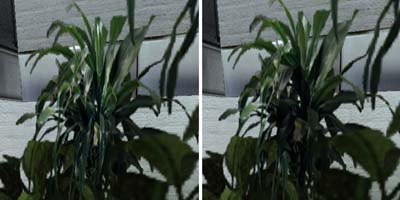
Here we have a classic low-polygon-yet-complex-looking-plant, which is constructed by placing two alpha blended polygons with profile of a plant into cross like shape. Atypical problems with "normal alpha" sorting are clearly visible (see the middle of the plant). Like in here, even a small change in the viewing angle might make the polygons pop in front of each other and back again especially where the polygons cross.
To help the sorter, you can split the polygons from the crossing point. This usually brings good results, but produces also a lot more polygons to be sorted, which again is very bad speed-wise.
Alpha test
You can find a menu item called alpha test from the material pop-up palette, which can be turned on or off for alpha blended materials. The name, alpha test, refers to the technique which is used to determine the transparency of the alpha blended pixels. To fully understand the the difference between "normal" alpha and alpha test requires some extensive technical explanations which we'll skip now.
However, in short, alpha test is originally designed to be used with alpha maps which have clear on/off situation, like a row of bars or wire fence. The good thing about alpha test is that they are sorted with Z-buffer, which makes them very fast to draw, pretty much as fast as any opaque polygon drawing and also no popping like in traditional alpha should occur.
What is special about alpha test inside Max-FX is that you have a chance to set the alpha test reference value. That is the grayscale (0-255) value which is used to determine the threshold, i.e. the value where the alpha is considered as fully opaque or fully transparent in sense of the sorting. You can set this value as general value in MaxEd from the local preferences. Inside game, this value is checked from the materials.txt file and it can be separate for each material category.
Interesting here is that alpha test reference value does not simply define an absolute value where the transparency is on or off. For example, if we set the reference value to 128, the values below it will be cut off (not drawn), but the values between 128-255 are semi-transparent as usual. So, what is the problem? Why not turn the reference value all the way down to 1 and have the full scale of transparency in use?
On top of normal geometry that would work -- the "absoluteness" of the value is mostly visible when two alpha test -textured polygons go on top of each other. Because the way Z-buffer operates, having two alpha polygons on top of each other might "overshadow" the one behind and even the lightest transparency might leave the further alpha test indrawn. Study the pictures below to learn more.
Note: As said, MaxED shows all materials using the same reference value, which can be adjusted from the local preferences. Remember, that MaxED can not change the alpha test ref -value runtime, you change only takes effect after quitting and restarting MaxED.
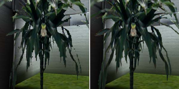
Here on the left you see an example of alpha blended plant (alpha test on, of course) with high reference value (254). This plant is not an good example of proper use of high threshold, as the plant with it's curved forms requires much bigger resolution for the alpha map, which also is not designed with this level of threshold in mind. However, it demonstrates how there is no semi-transparency visible. With this threshold, orthogonal metal bars or a very systematic wire fence with much smaller unit size (thus higher resolution) would be much better example.
On the right is the same view with medium alpha reference value of 128 which seems to be bring very good results: the plant seems to have much higher resolution, it blends to the background to some extent and even consecutive alpha maps do not bring too obvious "rims" (see below).
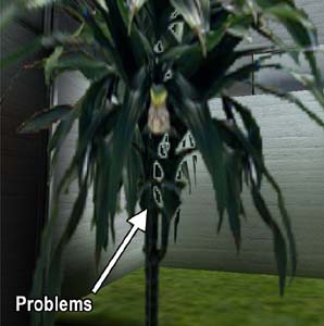
Here above we have the same plant again with low alpha test reference value (5). This introduces "no-draw rims" to some areas where consecutive alpha maps are visible (as you see, the blending with normal geometry works perfectly with nice semi-transparency). The arrow points to problems that might occur and sometimes seem very obvious: the drawing order of the two transparent polygons inside the Z-buffer makes the first alpha test polygon to overshadow the drawing of the second alpha map, which does not "kick in" before the alpha map reaches the value below the reference value of 5. This problem is visible only when the polygons happen to be in certain order. In the middle the polygons cross and and the left side works correctly (as the drawing order changes).
Naturally it is always best to try to avoid semi-transparency and consecutive alpha test polygons. How big of a problem it really is, depends. If, for instance, you have an alpha test blended window and you look through it to to a room filled with alpha test plants, by chance, they might be drawn in the right order and look perfect, or then the plants might completely disappear. Unfortunately there is is no way to know or control in which order the polygons are drawn in Z-buffer and how they might or might not overshadow each other.
So, to the question "Should alpha test be on?" Answer is "Yes, almost always". The fact is, that you are mostly better off with alpha test because of the speed and sorting being solved. And as long as you do not place many lightly opaque alpha mapped polygons with low reference values into same room, you should not even see much drawing problems and they mostly are much less obvious than the annoying sorting problems of the normal alpha blending.
Alternative blending methods
In addition to alpha blending and alpha test, Max-FX offers two more possible ways to do a sort of a transparency: additive and multiplicative blending. Both blending methods can be assigned to a polygon that has any material (except with already alpha blended texture). In other words, multiplicative and additive are qualities of polygons, not materials. If you are acquainted with some 2D graphics software, you might know the blending methods with the names 'screen' for additive and 'multiply' for multiplicative.
Multiplicative blending can be assigned to a polygon by pointing it in the F6 (texture) mode and by pressing M. In multiplicative blending, the texture is mixed to background so that it can only darken what is behind. The texture of the polygon is handled so that white is fully transparent and black is fully opaque. The darker the color is, the more it affects and if the texture has colors, each RGB channel affects accordingly.
Additive blending can be assigned to a polygon by pointing it in the F6 (texture) mode and by pressing A. In additive blending, the texture is mixed to background so that it can only lighten what is behind. The texture of the polygon is handled so that black is fully transparent and white is fully opaque. The paler the color is, the more it affects and if the texture has colors, each RGB channel affects accordingly.
You can turn polygons with either blending methods back to normal solid geometry by pointing it and pressing S. Neither multiplicative or additive blended polygons have lightmaps usually returning to solid requires re-rendering of the lightmap. You should also notice, that usually copy/pasting objects with multiplicative or additive polygons will turn them into solid rendering mode.
Dualsided or not?
Transparent materials are often used in places, where both front and the back sides of the polygon should be visible. Rarely, you might also create something non-alpha geometry, which you would like to appear to have both sides. In these situations, you might consider tagging dualsided flag on by right-clicking the texture. This will remove the backface culling from that material, and in other words, make it to be rendered as dualsided.
Polygons textured with dualsided material (alpha blended or not) have lightmaps as any other polygons do, and the lightmaps are combined with main texturing as usual. You should notice, that there is only one lightmap, which is calculated during radiosity rendering according to the normal of the polygon (just like the normal single sided ones). This might sometimes raise lighting problems. Think of having an alpha blended dualsided wire fence in the middle of a room where the other side of the room has all the light. If the normal of the fence polygon is pointing towards the bright side when the radiosity solution is rendered, the fence might appear too bright when the player goes to see it from the darker side (or vice versa, naturally).
The solution could be to take the dualsided flag off from the material and manually construct two polygons on the same spot with the other's normal pointing towards the dark side and the other to the light side, thus producing a separate lightmap for both sides. In this case, the dualsided can not be on, or these two polygons will interfere with each other producing heavy-duty Z-fight.
Quite often happens that same material is needed sometimes as dualsided and sometimes not. A good solution is to create a copy of the material and have the other as singlesided and the other as dualsided. MaxED can handle these multiple instances of an material without using extra texture memory.
Would it not be useful to turn everything dualsided and never worry the directions of the polygon normals? Here we have an example: backface culling is very useful feature, as in average, half of the polygons that make an object are automatically optimized. The object on the left is single-sided, and only the polygons that are visible are drawn. The object on the right has dualsided on, and all of it's polygons are always drawn, even if that does not bring any visible change. Dualsided polygons may also be problematic with collisions, as the collisions are only checked against the polygon on the side that the normal is pointing.
Planar mapping
In addition to more single polygon based texturing functions, MaxED offers the possibility to use sometimes irreplaceable technique called planar mapping. With planar mapping, you can project a texture to selected group of polygons that can be in almost any angle. Imagine that you would cast an image with a slide projector to an uneven surface and freeze that image as a texture.
Planar mapping requires the desired polygons to be a part of a polygroup. To define a polygroup, you have right-click the desired object (or a room) in the hierarchy list and select create polygroup. A question is presented where you have the chance to automatically include all the polygons under that hierarchy into the polygroup. The polygroup object appears under the object (or a room) that it belongs to and is sorted on top of the list. After creation, the polygroup indicates the amount of polygons currently in the group in brackets. You can select or deselect only polygons that belong to object that the polygroup is directly attached to or objects that are in the same level or lower in hierarchy. Selecting and deselecting polygons happens by first activating the name of the polygroup in the hierarchy list and then clicking polygons in texture (F6) mode while pressing shift. Selected polygons are shown with green translucent highlight.
After the desired polygons are selected, while the polygroup still active in the hierarchy, press N to enter planar mapping mode (you have to be in the F6 mode still).
Now doing usual texturing operations for one polygon affects all polygons in the group. The direction of the planar mapping is the normal of the polygon which you manipulate. You can rescale, rotate etc. As you might notice, in some cases you may have to move the texture a bit for the texturing to be updated in the other polygons. Avoid pressing LMB unintentionally, because that will be considered as reset, and the mapping goes back to default scale.
Here we have an example with a strange half-sphere bump on the floor. The floor and the sphere have been assigned to a polygroup and when the floor is textured in planar mapping mode, the same texture is projected to the polygons of the sphere. Study the example level to learn more. For instance, go to F6 mode, activate the polygroup from the list, press N and move the texture on the floor.

More about polygroups
This is not actually a texturing issue, as polygroups can do some other things too: They can be used to make the meshes appear smoother. This is handy option especially for all round objects, like pillars, barrels or spheres.
After selecting the smoothed surfaces with polygroup (for instance, the sides of a barrel), right-click the polygroup name in the hierarchy list and select smooth lightmaps to make the rendering (normal rendering, preview will not work) to smoothen the lightmap edges to appear more like the barrel would be truly round.
Sometimes, you might also want to make the mesh itself appear smoother and then you can select Smooth geometry from polygroup properties (right-click). This will not be visible inside MaxED, but the game engine will create a subdivision surface solution of the surface (the game's geometry detail level must be set to high).
You can study the different properties of subdivision by changing the Set max angle and Set max edge length values from the geometry smoothing submenu (under the RMB menu of a polygroup). Max angle basically will make the subdivision to occur, if some angle in the polygroup area is more than the given value. Max edge length will make the surface to be subdivided, if polygon edge is longer than the given value.
Smooth surface can easily make very big amount of polygons, and you should carefully think that where to use it and to what extent. Although subdivided polygons are not very expensive rendering-wise, each polygon added brings always a little more slowdown.
Light layer
Light layer is a small special feature in MaxEd, which was mainly designed to help creating large outdoor buildings (at night with lit windows). Light layer is an additional texture which is attached to material, but it is not something that is applied in-game like lightmaps or detail textures. Light layer is basically an additional mapping which can be used easily to modify lightmaps by applying them after radiosity rendering in MaxED before exporting the the level.
The light layer can be added to a material by right-clicking it from the material palette and selecting Add light layer.... This let's you pick a texture for the light layer. The light layer is visible and can be modified in light layer rendering mode, which can be toggled prom the preferences (Ctrl+P) or by toggling it from the numpad division (/) -key, which cycles through different mapping methods.
You can use normal texturing operations to light layers (rotate, scale, copy mapping coordinates etc.). Note that it can be of completely different proportions than the main texture. Usually, for large outside buildings, it is wise to make light layer to repeat much less (ie. larger) than the actual texture, to give the sense of main texturing not tiling so much.
Here we have a rendered room with a repeating light-like wall texture (top left). A special light layer texture is made, attached and textured to the surface so that repeats only every fourth time than the actual texture does (top right). Then, the light layer is applied to the lightmaps (below left), which gives us the final appearance (below right).

Light layer is calculated to the actual lightmap by either selecting the single polygon in F6 mode and picking Add light layer to lightmap. Alternatively by first selecting all the desired objects in F5 mode, then going to F6 mode and applying "add light layer to lightmap" on one of the light layered polygons, like before, will add all the light layers in all the objects that were selected. This option is naturally available only if there is a light layer in the texture that is pointed in the F6 mode.
Light layer modifies the actual texture so that mid-gray does not change anything, full white makes the lightmap texels completely white and black completely dark. Any color values will also give similar results (ie. full red will make the lightmap full red). Usually rather modest color changes from mid-gray will give good effects. Study the example above and see how it affects the main texture once applied.