Boolean operations
In this tutorial we look at Boolean operations (name derives from George Boole, a mathematician). If you have previous experience on some 3D-software, you are probably acquainted with Booleans already. For a first timer this might sound a bit intimidating, but the concept is a very simple one.
There are three main operations. Union and subtraction are, in simple terms, just about adding pieces to objects or taking away pieces from objects, respectively. Intersection is a sort of combination of the two; two objects are aligned so that they intersect, and then all the geometry except for that included in the intersection is removed, thus creating a new object. Under Boolean operations menu in MaxED, you can find a fourth operation called join, but it is not exactly a Boolean operation. A brief explanation of that in the end.
First we'll go over a few requirements for the objects being Booleaned, then look at each of the operations more specifically, and finally cover two ways to keep your geometry good and clean.
All of the examples are carried out in a singe room that has an exit in one corner
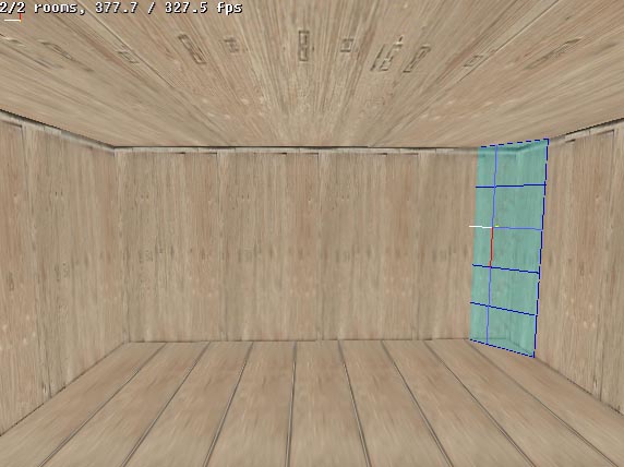
This way we'll have what is, for MaxED, a proper room structure, and we can have all the example objects grouped to this, getting rid of the red bounding boxes that surround ungrouped objects.
The Requirements
Boolean operations can only be performed with objects that meet these requirements:
- The objects have to be on exactly the same level in the hierarchy tree. A good way to get object A to the same hierarchy level with object B is to first group A to be B's child, and then lift it up one level: (in F5 mode) -click object A, press "G" and click object B -click object A, and press SHIFT-G
- Both objects must have their polygons facing the same way: in or out. As was briefly mentioned in the "Creating your first level" -tutorial, in MaxED object's polygons can be pointed either outwards for normal solid-looking objects, or inwards so that they can be viewed from inside the object, which is how rooms are done. Looking at an object in MaxED, it's easy to tell which way it's polys are facing, unless the object's texture has been marked dual-sided. A polygon whose texture has been marked dual-sided looks the same from both sides. In this case you might want to disable the dual-sidedness (right-click the texture in the materials menu and remove the dual-sided -tick).
- At least one of the objects has to be static. You can not do a Boolean operation on two dynamic objects.
The Operations
Booleaning is done in F5-mode by selecting one of the objects, pressing U, S or I (for union, subtract or intersect, respectively), and selecting the other object. In a Boolean operation there are always two objects involved.
UNION - In a union operation, two objects are put together so that from MaxED's point of view they become one single physical object. Actually a more correct term would be "addition", since one of the objects retains it's identity, and the other is added to that. Which object's properties are used, depends on the order in which they are selected in the operation, unless one of them is dynamic and the other static - in that case the dynamic object's properties are always used.
The objects can be aligned in any way. If they intersect, the intersecting parts of the objects are discarded. If they touch, the touching parts of the surfaces are again removed for the same reason. If the objects do not touch at all, nothing visible is done, the objects will simply from thereon be handled as one object.
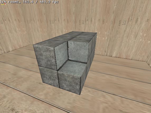
Example of a union between two objects that intersect.
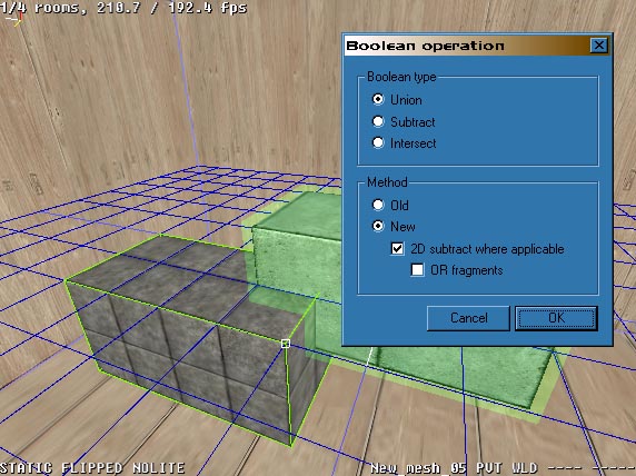
One of the objects is selected, "U" is pressed to specify a union operation, and then the second object is selected. The Boolean dialog pops up with the radio button selector ready on the union operation. When OK is pressed, the operation is carried out.

Now the objects have been merged together. When selected, the bounding box surrounds the whole object to signify this.

To illustrate how the extra intersecting geometry is dropped, in this picture the resulting object's polygons are flipped (CTRL-F in F4-mode when pointing at the object) to point inwards, and the object is inspected from inside. You can see from one end of the object through to the other.
Note that if the unioned objects do no touch at all, the union operation can be undone by pointing at one of the objects in F4-mode and pressing P. This will lead to the object being divided back into two separate objects in the following manner:
tempobject (static) --> tempobject01 (static) (pointed when P is pressed)
tempobject02 (static)tempobject12 (static) --> tempobject13 (static) (pointed when P is pressed)
tempobject14 (static)tempobject (dynamic) --> tempobject (dynamic)
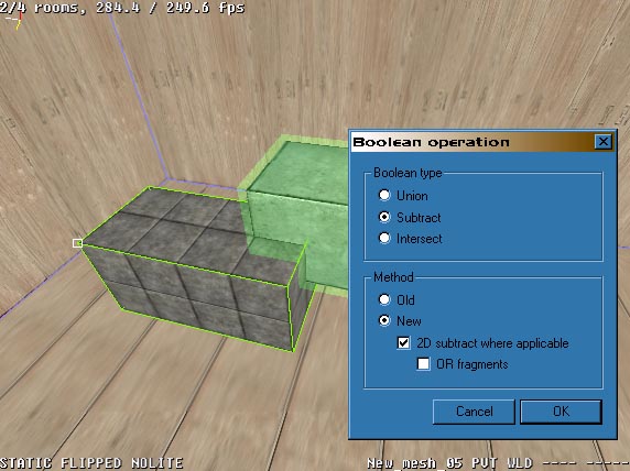
tempobject01 (static) (pointed when P is pressed)SUBTRACT - In subtraction, one of the objects functions as a "negative", that is used to subtract geometry from the other. The objects are aligned so that their intersection matches the piece that needs to be removed.
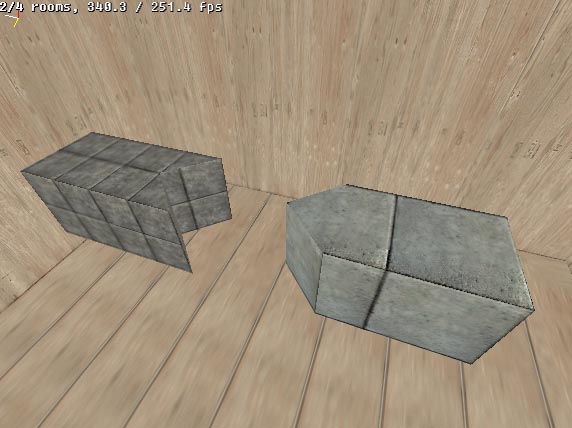
Following the above, here the two objects are again aligned so that they intersect each other from corners.
As you can see, the resulting cavity has the same texture with the same settings on it's polygons, as the negative object that was used in the operation. This is because these actually are the polygons (or rather, parts of polygons) of the negative object, merged with the target object.
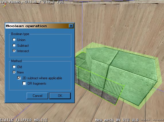
INTERSECT - This is a mix of sorts between subtract and union. Like in subtracting, the two objects have to intersect for the operation to make sense, the only difference is the end result. The end result of an intersect operation, like it's name suggests, is only those volumes of the original objects that intersected each other. So, where in a subtraction two objects are intersected to specify a piece to be removed from the other, in an intersection everything _except_ that piece is removed.
Here the objects have been modified slightly to illustrate the workings of an intersection
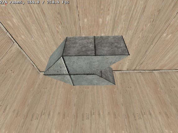
The arrowheaded object is lifted halfway on top of- and into the arrowtailed object.
The result is an arrowheaded and -tailed object with half the height of the original objects.
JOIN - As mentioned before, a join operation is not a true Boolean operation. It does the same as a union but with a different twist: it does not delete any geometry. As explained above, in a union all intersecting geometry is discarded, in a join however the objects are just clamped together keeping all the geometry intact. The objects can also be separated again if necessary even if they touch (unlike in a union). The only requirement is that the objects' vertices must not meet, if this happens, separation will likely fail.
Joining is useful if you have many objects that would be better handled as one, but you want to be able to separate them if necessary. Depending on the case, joining might actually produce more optimized geometry than a union. Like in the case of a plank pile, joining will result in fewer polygons than a union since union splits the surfaces but joining doesn't.
Lightmaps - You should know, that Boolean operations sometimes destroy the lightmaps of those faces which are modified and re-rendering might be required.
Stay out of trouble
Boolean operations are the key to any geometry in MaxED, and you are likely to make them all the time. In a perfect world, this should always work. However, MaxED uses floating point calculations and representations with it's geometry, and although it is a very accurate way, there are inevitably some limits. The unfortunate fact is, that with this system you would need a computer with infinite accuracy and infinite amount of memory to produce mathematically perfect results with each Boolean operation. And if the result is not perfect, there has to be some approximation and tolerances, and that means there can be problems. There are a few things that you should try to do/avoid to stay away from trouble.
KEEP BOOLEANS TO MINIMUM - Each Boolean operation forces the system to rebuild the geometry, and may eventually cause those small incrementing inaccuracies to turn into errors, sometimes even crashing. A good policy is to always save your stuff before complex Boolean operations
Do not get this wrong, as Max Payne the game is modeled almost fully with MaxED, you know that there are complex objects and other geometry that has required dozens of Boolean operations to create -- apparently with success. So, do not be afraid of Booleans, but if you can minimize the amount, it is usually preferable.
USE ABSOLUTE GRID TO AVOID INACCURACIES - As said, it is not advisable to blindly trust that your geometry will maintain perfect integrity after any Boolean operation. For instance, the floor that you think is perfectly horizontal, might be microscopically tilted. Aligning the grid to this polygon and creating new outside wall, for instance, would make it tilted too. If you pull this wall very far up (this is a skyscraper, say, 300 meters tall), the tilting error builds up and the upper edge of the wall could be already something like a quarter of a centimeter away from the correct vertical position. Then you might Boolean the wall and the floor together and further copy the whole thing as an extension to the building another 300 meters up. If you now try to Boolean the stuff together it's likely to not work, as the geometry does not "reach".
The way to prevent this is to use absolute (world) grid alignment whenever possible, in which the grid can be aligned to three different angles (one for each axis of the coordinate) and to a distance from the world origo (the centerpoint of the space in which the map is created) that is a multiple of the current grid size.
When absolute alignment is used to align the grid to a surface, it is aligned as close to it as it can be within these parameters. This way, whatever error might have been introduced to the geometry, it will not get incremented. Absolute alignment is done like normal alignment but with shift (in F4-mode, SHIFT-A). This will naturally encourage orthogonal geometry, but with practice and clever usage, this is not a problem even in more complex and slanted geometry cases.
FIX - Fixing (or "welding") makes MaxED to rethink the triangulation of the object. Fixing is a good policy after/before each Boolean, after splitting or joining faces and after moving/tilting some faces -- Almost always when geometry has been extensively modified. After Booleans, fixing usually reduces polygons and vertices.
Fixing is done in F5-mode by pointing at an object or a selection, and pressing "F". The weld tolerance is given in meters, i.e. 0.000500 (half a millimeter) for example, which is the default value.
In addition to polygon rethink, the weld tolerance setting tells MaxED to, within that selection, join together all vertices that are at maximum the given distance (the "weld tolerance") apart from each other.
If all vertices of a polygon are within the weld tolerance, that polygon will be entirely deleted. "Optimizing" faces with high fix values is not recommended policy. This might produce N-gons which are not planar and that usually makes gaps/errors in geometry if you make more Boolean operations. If you do not understand this brief explanation, then simply a good rule-of-the-thumb is: do not change the default fix value :-)
Fixing also creates new T-vertices, if necessary (we do not go into detail now). In practice, it means that in some cases fixing might also increase the polygon count if it serves to make the structure more robust.
More advanced Boolean examples
At first, general modeling possibilities may seem a little limited in MaxED, but with clever Boolean use, you can do very complex things. For instance, one FAQ must be how to make round or sphere-like forms, as there are no such primitives in MaxED.
To do complex things with Booleans, you have to learn to analyze your goal and try to find clever ways to construct them. For instance, let's say a barrel like form is your goal. Obvious solution would be to draw a round shape on the grid and extrude that. Naturally, it is hard or impossible to draw a round profile on a grid with steady edge length and face angle, so you you would have to approximate a little. This would already be rather OK barrel, but how to make a evenly rounded barrel shape where every face and angle on the outer rim is equally sized? Lets take a look...
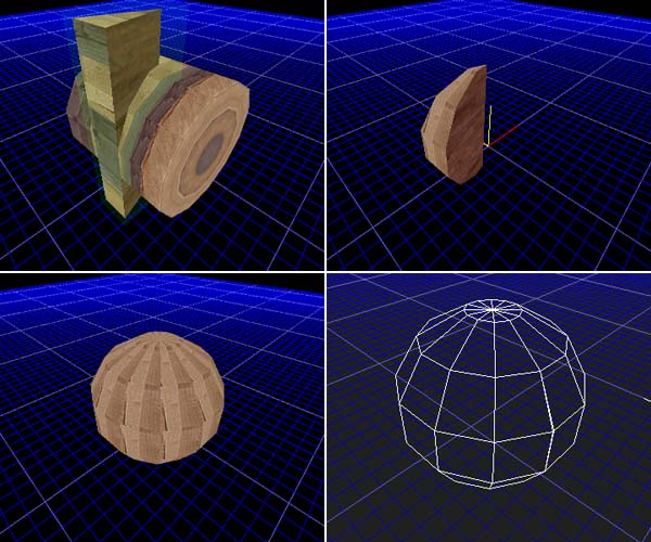
Start by drawing a box on the grid, for instance 3x3 units (this will be the radius of your sphere). Go to preferences (Ctrl-P) and select the keyboard tilt angle to be some figure which can be evenly multiplied to 360 degrees, here we use 15 degrees.
Use keyboard right-left cursors to tilt one face on the side. Check the top-left picture from below to get the idea. Turn the grid so that the plane goes through the edge which is active (red) in the this picture. Copy the object and mirror it. Make an intersect (I) Boolean operation between these two. The result should be a nice "slice of a cake" as seen in the top-right picture. This a clever way to make a this kind of object where you can be sure that both sides are tilted exactly the angle that you intended and the radius of the forming sphere can be anything you choose.

The rest should be easy: copy the slice and rotate it by keeping the sharp point of the slice as you reference point. As your angle snap is still 15 degrees, it is easy to keep the 2-key pressed (Y-axis) and rotate the copy of the slice two clicks and make it meet the neighboring piece exactly. Now you can make a Boolean union (U) between these two. Then copy that piece again and carry on until you get a full nice round figure with same sized edges and angles as seen in below-left image. Remember to fix (F) the object from time to time between Booleans.
By extruding and texturing the shape you can create a pipe or a barrel or what have you. Sometimes, it may be easier to texture the first single slice before the Boolean operations to get the exact repeating texture to each section (if that is your goal). Having texture smoothing or even geometry smoothing with the aide of a polygroup should give you better and smoother appearance (see advanced texturing section).
A sphere may seem too hard to produce, but actually by modifying the barrel idea a little bit, it is rather easy.
By turning the previous barrel horizontal and making another tall 15+15 degree "slice of a cake" you can create the basic form. Place the objects as seen in the top-left image, and make a Boolean intersection between them. This should produce a form as seen on top-right image.
Now, as you did with the barrel, rotate this piece around and make necessary Booleans and fixing to produce a nice, exact sphere as seen below-left and, in wire-frame, below-right.
By starting with different initial angles like 7.5, 10, 6 etc. you can create more/less detailed spheres or spheres with different divisions. 15 degrees is rather good as the top and sides of the sphere are straight and it is easy to fit this sphere to orthogonal world of boxes and other items drawn by the grid which is what most of the level geometry usually is.